We can calculate your ventilation system capacity for regulatory compliance & determine unused capacity for process expansion.
Dust Collection & Ventilation System Calculations & Sizing
Industrial Ducting System Design
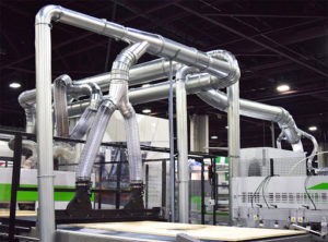
Industrial duct systems are used for the supply or exhaust of air-streams in industrial operations. Ductwork can be under positive or negative pressure to convey clean air to work areas and contaminated air away from applications causing contamination to the surrounding air. Ducting systems are constructed mainly of metal and assembled together with flanges, clamps, slip fitted or welded. Duct systems include straight lengths or sections of duct, transitions, elbows, and bends, enlargements or contractions, hoods, discharge stacks, and hangers or supports.
Ducting system design is important to properly convey particulate-laden air without depositing the particulate material, at a design velocity with minimal pressure loss using a properly-sized fan horsepower to minimize power consumption and costs.
Dust Collection System Design Calculations
Dust collection system design calculations can be very complicated but important for meeting regulations and worker safety. AST Engineering experts will visit your plant and review your application in details. We will follow the steps below for calculation and sizing the dust/fume/mist collection system:
- Draw a floor plan of your shop
- Determine Duct Velocity (FPM)
- Determine the Diameter and CFM of each Branch
- Determine the Diameter and CFM of Main Duct
- Calculate System Resistance (SP – Static Pressure)
Once completed, proper sizing calculations can be completed to determine compliance regulations & safety criteria or available capacity for process expansion.
Important Terms to Remember
- CFM – Air Volume in cubic feet per minute.
- FPM – Velocity of Air in feet per minute.
- SP – Static Pressure. This is expressed in inches water gauge. It is resistance to air at rest in a duct, and is also commonly called “resistance,” friction,” “friction loss” or “pressure loss”.
- VP – Velocity Pressure: expressed in inches water gauge. It is kinetic pressure in the direction of flow necessary to cause air at rest to flow at a given velocity.
Properly Sizing Your Dust Collector
To properly size a dust collector, we need to know your CFM requirements and at what Static Pressure your system will be operating. Use the CFM and Static Pressure to compare the performance of your dust collector. The dust collector performance ratings should show that at your given Static Pressure, the CFM it will provide.
The first step in designing your system is to draw a floor plan of your shop area including the following:
- Location of dust producing machines, indicate size & location of dust pick-ups on each machine. Remember – Machines with the biggest draw (highest CFM) should be placed nearest to the dust collector.
- Desired location of dust collector unit.
- Floor to joist measurement.
- Any obstructions that would interfere with the run of the duct.
For the rest of the steps, AST Engineering uses Industrial Ventilation Manual (ACGIH), Ontario Fire Code (OFC) and NFPA.
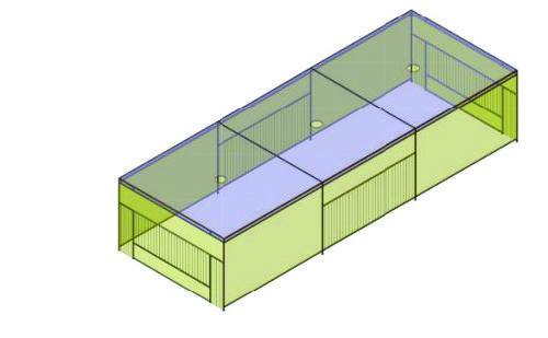
Sample Calculation
Airlow Calculation – Hood #1
V1 = (202+190)/12 x 216/12 x 128/12 = 9341 cu.ft.
VT = V1 + V2 = 17366 cu.ft.
QT = 28000 cfm
Q1 = QT x V1/VT = 28000 x 9341/17366 ~ 15000 cfm
n = Q1/V1
= 15000/9341
= 1.6 air changes/minute
DT = 60/1.6 ~ 38 sec. (i.e. an air change every 38 seconds)
Based on the experience, heavy duty welding applications need and air change every 25 – 45 seconds. So the above calculation is within this range.
A1 = (P1 x 4in.)/144
= [2 x(202+190+190+216)] x 4 / 144
= 44 sq.ft.
V1 = Q1 / A1
= 15000/44
= 340 FPM (which is greater than 100-200 FPM)
Based on Industrial Ventilation Guidelines (ACGIH) the minimum capture velocity for welding fume is 100 FPM
Ranges of Capture (Control) Velocity
| Conditions | Examples | Capture velocity, m/s |
|---|---|---|
| Released with essentially no velocity into still air | Evaporation from tanks, degreasing, plating | 0.25 to 0.5 |
| Release at low velocity into moderately still air | Container filling, low-speed conveyor transfers, welding | 0.5 to 1.0 |
| Active generation into zone of rapid air motion | Barrel filling, chute loading of conveyors, crushing, cool shakeout | 1.0 to 2.5 |
| Release at high velocity into zone of very rapid air motion | Grinding, abrasive blasting, tumbling, hot shakeout | 2.5 to 10 |
Note: In each category above, a range of capture velocities is shown. The proper choice of value depends on several factors:
| Lower end of range: | Upper end of range: |
|---|---|
|
|
|
|
|
|
|
|